


The PS4IoT Smart Power Module
1120грн. – 1845грн.
PS4IoT is an uninterruptible power supply module with battery charging and protection, for building smart devices with power paths’ redundancy, with 3.0 to 6 volts and 3V3, 5V or 12V output voltages, with total power up to 5 watts.
The module is designed for use in electronic devices based on any microcontroller platform, such as ESP8266, ESP32, Arduino, STM32, and derivative boards ( ESP12.OLED, NodeMCU, etc.) as an autonomous or software-controlled power supply unit.
Features
- Start from AC/DC adapter when the battery is deeply discharged;
- Start from AC/DC adapter when there is no battery;
- Automatic battery charging and simultaneous use of the device;
- Possibility to replace the battery without interrupting power from the AC/DC adapter;
- When powered by the AC/DC adapter, the battery is not connected to the load, which saves the number of charge-discharge cycles (prolongs battery life).
Capabilities of the module with basic settings
This tiny module may surprise you with many important and interesting functions. PS4IoT_V1 with basic settings provides:
- Automatic online switching “battery-mains” and vice versa, without interruption of output voltage generation (12V, 5V, 3V3) of loads;
- Automatically switches to AC/DC adapter 5V when the battery is disconnected without interrupting power to the loads;
- Automatic battery charge/discharge control; Default charge current is set to 0.5 A. The state of the battery charging process is displayed by two LED indicators.
Module application profiles
The module can provide the following profiles for autonomous and controlled use as part of a smart device:
- a battery-free device powered only by an AC/DC 5V adapter;
- a device powered by Li-Ion battery and AC/DC adapter 5V
- a device with rechargeable Li-Ion battery only;
- a device with fault-tolerant redundancy of 3 power supply paths.
Description
Purpose and compatibility
PS4IoT is an uninterruptible power supply module with battery charging and protection, for building smart devices with power paths’ redundancy, with 3.0 to 6 volts and 3V3, 5V or 12V output voltages, with total power up to 5 watts.
The module is designed for use in electronic devices based on any microcontroller platform, such as ESP8266, ESP32, Arduino, STM32, and derivative boards ( ESP12.OLED, NodeMCU, etc.) as an autonomous or software-controlled power supply unit.
Features
- Start from AC/DC adapter when the battery is deeply discharged;
- Start from AC/DC adapter when there is no battery;
- Automatic battery charging and simultaneous use of the device;
- Possibility to replace the battery without interrupting power from the AC/DC adapter;
- When powered by the AC/DC adapter, the battery is not connected to the load, which saves the number of charge-discharge cycles (prolongs battery life).
Capabilities of the module with basic settings
This tiny module may surprise you with many important and interesting functions. PS4IoT_V1 with basic settings provides:
- Automatic online switching “battery-mains” and vice versa, without interruption of output voltage generation (12V, 5V, 3V3) of loads;
- Automatically switches to AC/DC adapter 5V when the battery is disconnected without interrupting power to the loads;
- Automatic battery charge/discharge control; Default charge current is set to 0.5 A. The state of the battery charging process is displayed by two LED indicators.
Module application profiles
The module can provide the following profiles for autonomous and controlled use as part of a smart device:
- a battery-free device powered only by an AC/DC 5V adapter;
- a device powered by Li-Ion battery and AC/DC adapter 5V
- a device with rechargeable Li-Ion battery only;
- a device with fault-tolerant redundancy of 3 power supply paths.
Smart power supply module formula
Online Uninterruptible Power Supply Unit module
- With automatic charger and selectable power source;
- Intelligent and connected;
- With power source redundancy layout;
- Fully autonomous or sufficiently managed;
- With or without a battery;
- For pockets or stationary;
- With simultaneous charging and power supply of load;
- Indoor or outdoor;
- In inexpensive and miniature design;
- Best suited for smart devices and IoT;
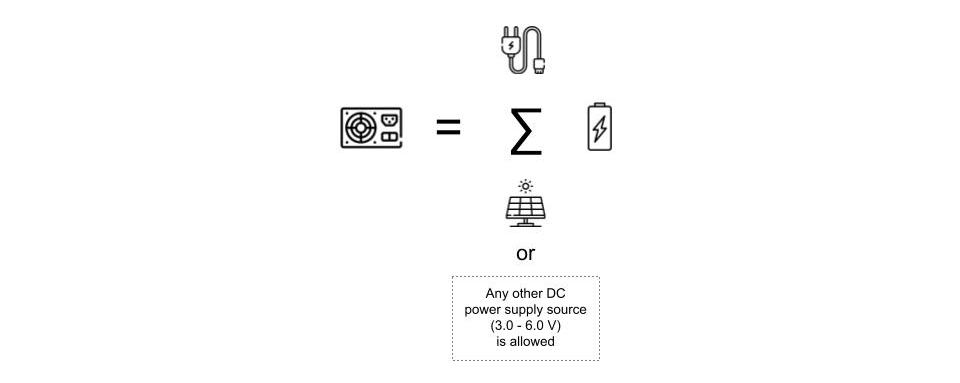
As you can see from our “formula”, you can simultaneously power one or more payloads, connect a controller with any functionality to the module according to your design idea – in other words, you can create the most demanding portable and stationary devices using the PS4IoT_V1 module.
This module is a versatile component that will provide reliable power, observability and controllability for your DIY or even commercial product.
PS4IoT acts as an intelligent intermediary between the load and all available power sources.
This power supply automatically protects the device and the battery, providing consumers with the ease and simplicity of using the end device in a way that is only found in high-quality and high-tech smartphones.
Module functions
| Automatic mode | Managed by MCU mode | |
| Battery-free operation | Yes, auto | Yes, auto |
| Starting with a deeply discharged battery | Yes, auto | Yes, auto |
| Simultaneous battery charging and power supply of loads | Yes, auto | Yes, auto |
| Automatic battery charging | Yes, auto | Yes, auto Or by means of the controller via CEset |
| Choice of power supply paths | Yes, auto | Yes, auto |
| Battery charging enable and disable control | Yes, with a jumper | Yes, by means of the controller via CEset |
| Disabling the built-in status indicators | Yes, with a jumper | Caution! It is forbidden to switch on the status LEDs in managed by MCU mode |
| Electronic main switch | Mechanical, manual only | Mechanical, manual only |
| External power failure detection | Yes, with built-in indicators | Yes, by means of the controller using the status signals CC, CP, CEset.1 |
Battery protection and safety functions
| Automatic mode | Managed by MCU mode | |
| Battery overheating protection | No | Possible by controller means via an optional I2C, NTC, or 1-Wire battery thermometer using the 4-pin AUX pass-through interface. |
| Deep discharge protection | Yes, auto when below 2.3V | Yes, auto Or by monitoring the battery voltage level via the ADC of the controller and switching to deep sleep mode. |
| Battery overcharge protection | Yes, auto when exceeding 4.2V | Yes, auto Or controlled by the controller |
| Battery charge termination | Yes, auto | Yes, auto Or controlled by the controller |
| Temperature compensation feedback of the charging current regulator | Yes, auto | Yes, auto |
Module block diagram
Software monitoring of Li-Ion battery charging status
PS4IoT_V1 has a number of signal lines that allow the main controller to monitor the charging process status, temperature, and battery voltage programmatically. For example, if a mismatch is detected, such as exceeding the charging time or battery temperature, the controller can programmatically stop or restore the charging process. In addition, these mechanisms in combination with the sleep mode are reasonable to use in the charge/discharge control software algorithm to extend battery life.
Note. What if we make two interfaces at once on the GGreg20 module: pulse output and I2C? This would be very convenient, but the clients’ costs increase unnecessarily in that case. The companion controller occupies a certain area on the module board. The I2C bus occupies twice as many controller ports as the pulse output. All that adds significantly to the unit price. On the other hand, the pulse counting output interface takes up only one controller GPIO with an interrupt handler and is much easier to code. The current version of the GGreg20 module can work without a controller at all: a user can use a watch to monitor the duration of the radiation measurement and count led blinks manually. The PS4IoT_V1 version of the module does not support connecting an NTC battery thermistor directly to the charging controller. Therefore, temperature monitoring can be implemented by connecting an additional temperature sensor to the main controller using I2C bus or other interfaces such as 1-Wire, SPI, NTC-thermistor, etc. Thus, through the Charge Enable signal (see CEset.2) the controller can prohibit or allow charging depending on the battery temperature.
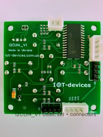
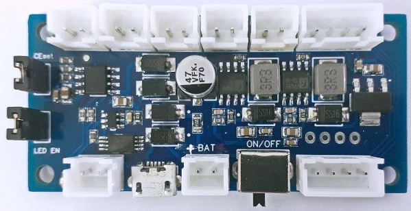
The interfaces are located on one side of the module
It is recommended to design the case of the device where you plan to install PS4IoT_V1 so that the bottom edge of the PS4IoT module board touches one of the outer sides of the case, as shown in the pictures. In that case
- Charge control LED;
- Power supply input 1 (μUSB);
- ON/OFF main switch;
- Aux spare interface – the connector for external devices;
can be used to organize a convenient interface to control the entire device through the user-provided mounting holes in the housing.
Cautions
Caution! Use quality batteries to obtain the declared technical characteristics of the product.
Caution! Use quality AC/DC adapters with appropriate cables capable of withstanding 5 volts with a load of up to 2 amps.
Caution! Maximum permissible load current:
- to the output 12V – 150 mA;
- to the output 5V – 1A;
- to the output 3.3V – 1A.
!! The maximum total load on the charger and outputs is up to 5 Watts.
Delivery sets
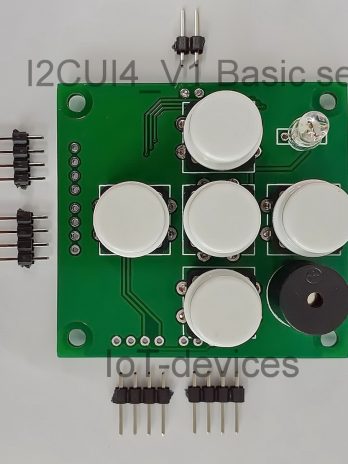
Set №1 – only PS4IoT_V1 module (Basic)
- PS4IoT_V1 module – 1 pc;
- Jumper on the board – 2 pcs;
- Pin connector 2.54 2P M, straight, included – 7 pcs;
- Pin connector 2.54 4P M, straight, included – 3 pcs.
Set №2 – module with connectors and cables (Basic + Connectors (installed) and cables)
- PS4IoT_V1 module – 1 pc;
- Jumper on the board – 2 pcs;
- Pin connector 2.54 2P M, straight, included – 7 pcs;
- Pin connector 2.54 4P M, straight, included – 3 pcs.
- Battery cable, flat, 15 cm, 2 wires, with connectors – 1 pc: 2P JST XH2.54 F – Dupont 2x1P F.
- Power output cable, flat, 20 cm, 2 wires, with connectors – 2 pcs: 2P JST XH2.54 F – Dupont 2x1P F.
- Charging status output cable CP&CC, flat, 20 cm, 2 wires, with connectors – 1 pc: 2P JST XH2.54 F – Dupont 2x1P F.
- Battery level output cable, flat, 20 cm, 2 wires, with connectors – 1 pc. 2P JST XH2.54 F – Dupont 2x1P F.
- JST XH 2.54 2P M connector, straight, on the board – 7 pcs;
- JST XH 2.54 4P M connector, angled, on the board – 1 pc;
- JST XH 2.54 4P M connector, straight, on the board – 1 pc;
Note : In this version, these connectors are soldered to the board and are ready to use with the appropriate cables.
Options № 3 – module with connectors and cables (Basic + Connectors (installed) and cables + AUX )
- PS4IoT_V1 module – 1 pc;
- Jumper on the board – 2 pcs;
- Battery cable, flat, 15 cm, 2 wires, with connectors – 1 pc: 2P JST XH2.54 F – Dupont 2x1P F.
- Power output cable, flat, 20 cm, 2 wires, with connectors – 2 pcs: 2P JST XH2.54 F – Dupont 2x1P F.
- Charging status output cable CP&CC, flat, 20 cm, 2 wires, with connectors – 1 pc: 2P JST XH2.54 F – Dupont 2x1P F.
- Battery level output cable, flat, 20 cm, 2 wires, with connectors – 1 pc. 2P JST XH2.54 F – Dupont 2x1P F.
- JST XH 2.54 2P M connector, straight, on the board – 7 pcs;
- Pin connector 2.54 2P M, straight, included – 7 pcs;
- Pin connector 2.54 4P M, straight, included – 3 pcs.
- JST XH 2.54 4P M connector, angled, on the board – 1 pc;
- JST XH 2.54 4P M connector, straight, on the board – 1 pc;
- Internal interface cable, flat, 15 cm, 4 wires, with connectors – 1 pc. 4P JST XH2.54 – Dupont 4x1P.
- External interface cable, flat, 30 cm, 4 wires, with connectors – 1 pc. 4P JST XH2.54 – Dupont 4x1P.
Note : In this version, these connectors are soldered to the board and are ready to use with the appropriate cables.
Attention. AC/DC adapter(s), battery pack, solar panel and temperature sensor are not included.
Full technical description: PS4IoT_V1 power supply unit description UKR , PS4IoT_V1 power supply unit description ENG
Module presentation: PS4IoT_V1 quick facts